Industrial production of urea
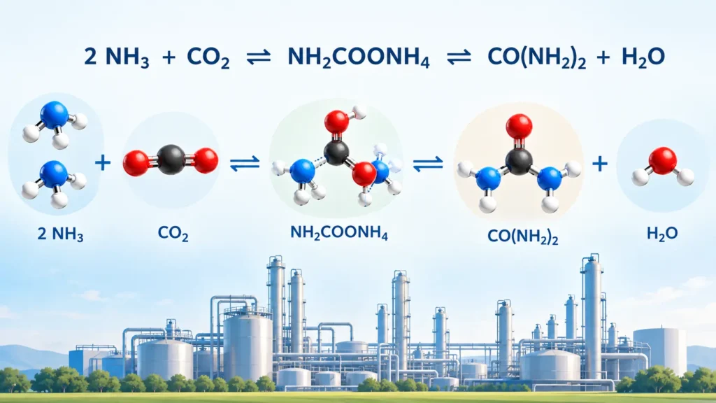
Urea is produced from ammonia and carbon dioxide at high pressure and temperature. Both feedstocks come from an ammonia synthesis plant. The carbon dioxide is a by-product stream vented from the CO2 removal section of that plant. Both feeds are delivered to the high-pressure urea synthesis section.
1. Fundamental chemistry of urea synthesis
1.1. The Bazarov reaction mechanism
In 1828, Friedrich Wöhler obtained urea from silver cyanate and ammonium chloride and correctly identified the product:
AgNCO + NH4Cl → CO(NH2)2 + AgCl
A substance known from living organisms was made for the first time from entirely inorganic materials. Many chemists therefore regard this synthesis as the birth of organic chemistry.
About 40 years later, the Russian chemist A. Bazarov, working in Germany, heated ammonium carbamate (NH2COONH4) for several hours under pressure in a sealed tube and obtained a small yield of urea:
2 NH3 + CO2 ⇌ NH2COONH4 ⇌ CO(NH2)2 + H2O
The conditions of this reaction were studied and optimized in the following years. The Bazarov reaction is now the basis of all large-scale commercial urea production.
1.1.1. Reaction steps, heat and operating conditions
The Bazarov reaction consists of two steps. In the first, ammonia and carbon dioxide form ammonium carbamate:
2 NH3 + CO2 ⇌ NH2COONH4 + A kJ —-(A)
In the second, ammonium carbamate dehydrates to urea and water:
NH2COONH4 ⇌ CO(NH2)2 + H2O − B kJ —(B)
The first reaction is fast and strongly exothermic. It runs almost to completion when the reaction heat is removed and the pressure is high enough to force NH3 and CO2 into the liquid phase. Its heat of reaction at 25 °C and 101.3 kPa (1 atm) is about 159 kJ/mol (38 kcal/mol) of solid carbamate.
The excess heat is usually removed by generating steam. The rate and equilibrium of this step depend strongly on pressure and temperature. The reactor pressure must be kept above the dissociation pressure of ammonium carbamate, which has been investigated extensively.
The second reaction is slow and slightly endothermic, about 31.4 kJ/mol (7.5 kcal/mol) of urea formed. It is an equilibrium reaction, so thermodynamics limits the urea yield. It takes place only in the liquid phase, and no catalyst is known to accelerate it. Since A is much larger than B, the overall formation of urea from ammonia and carbon dioxide is exothermic.
The feed mole ratio, water content, pressure, temperature and residence time determine how much carbamate converts to urea and water. With sufficient residence time, carbamate formation and dehydration proceed simultaneously for practical purposes.
These characteristics impose three constraints on any process based on Bazarov chemistry. First, an elevated temperature is needed to bring the second reaction to a reasonable rate. Second, both reactions run only in the liquid phase, and pure ammonium carbamate melts at 153 °C, which again requires elevated temperature.
Third, an elevated pressure is needed to force the normally gaseous feeds into the liquid phase at that temperature. In all commercial processes, the synthesis step ends at 170–220 °C and 125–250 bar.
1.1.2. Formation of ammonium carbamate
Ammonium carbamate is a white crystalline solid that dissolves in water. It forms at room temperature when ammonia gas is passed over dry ice. In aqueous solution at room temperature, it slowly adds one mole of water and converts to ammonium carbonate, (NH4)2CO3. Above 60 °C, the ammonium carbonate solution reverts to carbamate. At 100 °C, only carbamate is present in the solution.
The conversion of carbamate to urea begins above 100 °C, and above 150 °C ammonium carbamate loses one mole of water to form urea. Obtaining an appreciable amount of urea at 100 °C takes 20–30 h. The conversion rate rises with temperature. At 185 °C, about 50% of the carbamate is converted to urea in about 30 min. Ammonium carbamate melts and dissociates at about 150 °C. Its heat of fusion is about 16.74 kJ/mol (4.0 kcal/mol).
1.2. Conversion at equilibrium
The maximum equilibrium conversion to urea at 185 °C is about 53%, reached at infinite reaction time. Conversion can be raised by increasing the reactor temperature or by dehydrating ammonium carbamate in the presence of excess ammonia. Excess ammonia shifts the reaction toward urea. Water has the opposite effect.
1.3. Side reactions in urea synthesis (biuret formation)
Two urea molecules can react with each other and release one molecule of ammonia. The product is biuret:
2 CO(NH2)2 → NH2–CO–NH–CO–NH2 (C2H5N3O2) + NH3
Biuret and urea are similar in many properties, but biuret is an unwanted contaminant in most urea applications. Like the dehydration of carbamate, biuret formation is relatively slow. Limiting residence time and temperature where conditions favor biuret keeps its formation low. An excess of ammonia also suppresses biuret by pushing the equilibrium toward urea.
Urea can also decompose to isocyanic acid:
CO(NH2)2 ⇌ HNCO + NH3
2. Challenges in urea technology
Because the urea yield per pass is limited, full conversion of ammonia and carbon dioxide is possible only by recycling unconverted material. All commercial processes use the same basic chemistry. They differ mainly in the synthesis conditions and in the way unconverted material is recycled.
A successful design must combine high feed conversion, low energy consumption, low environmental footprint, low investment, high operating reliability and high product quality in one process concept.
Corrosion is a second challenge. The intermediate ammonium carbamate is highly corrosive toward steel, especially in the parts of the plant with the highest temperatures and carbamate concentrations. Long, uninterrupted production runs require a combination of process conditions and construction materials that prolongs the service life of equipment handling carbamate-rich solutions.
3. Production of urea by conventional total-recycle processes
The history of industrial urea production is almost as old as that of the nitrogen industry. The processes developed in the 1940s–1960s, now called conventional processes, made economical large-scale production possible in self-contained plants that did not depend on downstream processes to use unreacted ammonia.
The urea reactor gave enough residence time for the slow dehydration step to approach equilibrium. The reactor effluent contained urea and water together with unconverted ammonium carbamate, surplus ammonia and a small amount of carbon dioxide. Typical conditions at the reactor outlet were 200–250 bar and 190–220 °C. A large ammonia surplus was usual, and the NH3/CO2 ratio in the initial mixture ranged from 4.0 to 6.0.
Downstream of the reactor, the pressure of the synthesis solution was reduced, and the solution passed to a steam-heated medium-pressure decomposer. There the residual carbamate decomposed to ammonia and carbon dioxide, which flashed off as vapor at the lower pressure. The off-gases went to an ammonia–carbamate separation column, where distillation with pure liquid ammonia as reflux gave two products. The bottom product was an aqueous ammonium carbamate solution. The vapor top product was pure ammonia, which was condensed in ammonia condensers. To allow normal industrial cooling water for this condensation, the condenser pressure had to be at least 18–21 bar. This requirement set the lower pressure limit of the entire medium-pressure section.
The condensed ammonia returned to the reactor through high-pressure ammonia pumps, together with fresh ammonia from battery limits. The carbamate solution returned through high-pressure carbamate pumps. The ammonia recycle is virtually free of water, but the recycled CO2, present as carbamate, always brings water back to the synthesis section. Water lowers the urea yield per pass. In conventional processes, a high CO2 conversion per pass is therefore more important than a high ammonia conversion. This explains the high NH3/CO2 ratio. It also explains the heat balance, since the heat released by carbamate formation mainly heats the large ammonia recycle to the synthesis temperature.
After the medium-pressure section, a low-pressure recirculation section at 3–6 bar decomposed the remaining carbamate. The solution leaving it was virtually free of carbamate. An evaporation section then separated the urea–water solution into a urea melt and water vapor. Evaporation ran under vacuum to limit side reactions (biuret formation and hydrolysis). The melt went to the finishing section, usually a prilling tower in those days. The water vapor was condensed and steam-stripped in a desorber to remove remaining ammonia and carbon dioxide before leaving the plant.
4. Production of urea by stripping processes
Stripping processes were a major breakthrough. They are more efficient than conventional total-recycle processes and need less equipment. Their main characteristic is that the main recycle of unconverted carbamate and surplus ammonia takes place at synthesis pressure.
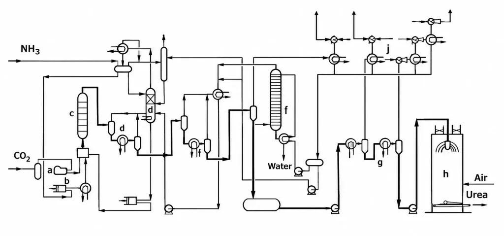
a) CO2 compressor; b) High-pressure ammonia pump; c) Urea reactor; d) Medium-pressure decomposer; e) Ammonia-carbamate separation column; f) Low-pressure decomposer; g) Evaporator; h) Prilling; i) Desorber (wastewater stripper); j) Vacuum condensation section
The high-pressure synthesis loop has three main steps, all at substantially the same pressure: urea reaction, stripping and carbamate condensation. Here, carbamate condensation means two combined actions. The supercritical (gaseous) NH3 and CO2 are transferred to a liquid phase, and they then react there to form ammonium carbamate. Some processes carry out the three steps in separate equipment items. Others integrate them partly in combined items.
The urea synthesis solution contains urea, water and unconverted material (carbamate, surplus ammonia and carbon dioxide). It goes to the stripper, essentially a high-pressure heat exchanger. Carbamate decomposes on the tube side at synthesis pressure and is heated by medium-pressure steam on the shell side. Most of the carbamate decomposes and passes into the gaseous (supercritical) phase. The off-gases go to the carbamate condenser at the same pressure.
The original stripping processes introduced either carbon dioxide or ammonia into the process side of the decomposer as a stripping agent. This agent promotes carbamate decomposition and vapor disengagement, and it gave the stripper its name. Thermal or self-stripping processes add no stripping agent. They are still classified as stripping processes because synthesis, decomposition of unconverted carbamate and carbamate condensation all occur at substantially the same pressure.
The carbamate condenser is also a high-pressure heat exchanger, cooled on one side by boiler feed water. The gases condense there, and the first Bazarov reaction, the formation of ammonium carbamate, takes place. The heat released is usually recovered as low-pressure steam.
In the various commercial processes, the NH3 and CO2 feeds can enter any of these steps, and either can serve as stripping agent. In some processes, the liquid ammonia feed also drives a liquid–liquid ejector.
The main difference from conventional processes is that the main recycle runs at full synthesis pressure through the gas phase and is therefore virtually free of water. Only a minor part of the unconverted carbamate and surplus ammonia returns as aqueous solution from the medium-pressure and low-pressure recirculation stages. The low water recycle gives stripping processes a high urea yield per pass.
Carbamate condensation also occurs at a much higher pressure than in conventional processes, so the heat released is at a high enough temperature for use elsewhere in the plant. Usually it produces low-pressure steam for carbamate decomposition, urea solution evaporation and wastewater treatment. Conventional processes used imported steam for all three. Stripping processes therefore reduced the energy consumption of urea production considerably.
Several stripping processes are offered on the licensing market. They differ in the type of stripping agent, the way feed and recycle streams enter the synthesis loop, the equipment design, the layout of the synthesis section and the degree of integration of the basic steps. More than 90% of all new urea plants are licensed by Saipem, Stamicarbon or Toyo Engineering Corporation. Saipem uses thermal stripping, and Stamicarbon and Toyo Engineering Corporation use CO2 stripping.
4.1. Stamicarbon CO2 stripping process
Stamicarbon, a Dutch company, introduced the first stripping process in the 1960s. In 1967, Petrus J. C. Kaasenbrood invented the high-pressure CO2 stripper, which revolutionized the urea process. The stripper has three main benefits. The carbamate can be recycled at synthesis pressure, so no extra water is needed for the recycle. No medium-pressure recirculation section is required. Condensing the strip gases in the high-pressure carbamate condenser produces low-pressure steam for downstream sections, which cuts the steam consumption of a urea plant by about a factor of two.
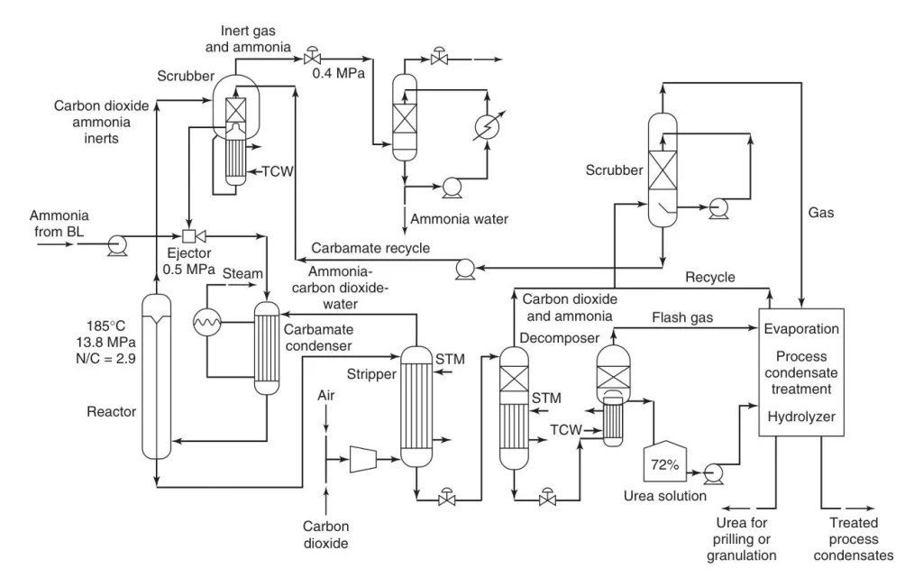
In this process, the CO2 needed for urea production enters the stripper as the stripping agent. The synthesis section of the first-generation plant has a reactor, a stripper, a falling-film high-pressure carbamate condenser and a high-pressure scrubber. Condensation in the high-pressure section is split between the condenser and the scrubber, which purifies the reactor off-gas. Gravity drives the recycle in the synthesis loop.
The reactor runs at 14 MPa (140 bar) with an NH3/CO2 molar ratio of 2.95/1 to maximize urea yield per pass. The reactor effluent is distributed over the tubes of the stripper, a falling-film shell-and-tube exchanger, and contacts the CO2 countercurrently. This lowers the partial pressure of NH3 and decomposes the carbamate efficiently at a relatively low temperature. The high carbamate removal efficiency means that no medium-pressure recirculation stage is needed. The urea solution leaving the stripper bottom flows to a single-stage low-pressure recirculation section at 0.4 MPa (4 bar). No separate ammonia recycle exists, so ammonia and CO2 conversion in the synthesis are equally important.
The stripper off-gas goes to the carbamate condenser. The carbamate formed and the uncondensed NH3 and CO2 enter the reactor bottom, where the carbamate converts to urea. The reactor is sized to give enough residence time for the reaction to approach equilibrium. Further condensation of gaseous NH3 and CO2 supplies the heat needed for the urea reaction and for heating the solution.
Noncondensable gases in the CO2 feed (passivation air) and part of the unreacted NH3 and CO2 go to the high-pressure scrubber. It typically has a shell-and-tube exchanger in the lower part and a packed bed in the upper part. In the lower part, most of the NH3 and CO2 condenses, and tempered cooling water removes the heat of condensation. In the upper part, the gases from the lower section meet carbamate solution recycled from the recirculation section countercurrently. The scrubber off-gas contains nitrogen, oxygen and very small amounts of NH3 and CO2. It passes through an absorber and is vented to the atmosphere.
The carbamate solution from the scrubber flows to a high-pressure ejector. The NH3 feed pressure provides enough head to convey it to the carbamate condenser. The wastewater system consists of a desorber and a hydrolyzer operating at 2 MPa (20 bar). Its output can typically serve as cooling water make-up or boiler feed water.
Near the turn of the millennium, Stamicarbon introduced the second-generation Urea 2000plus process in two variants, the pool condenser and the pool reactor. In 1994, the pool condenser replaced the vertical falling-film carbamate condenser with a submerged horizontal one, a liquid-filled vessel with a U-tube cooling bundle. Gas from the stripper (the CO2 feed and the off-gas from carbamate decomposition) is dispersed as bubbles into a bath of carbamate liquor and liquid ammonia feed. The incoming CO2 reacts instantly with the ammonia to form fresh carbamate. The change reduced the reactor volume by 34% and the carbamate condenser heat-exchange area by 45%. Equipment, structural steel and construction costs fell considerably.
Pool condensation offers two advantages. The bubbles create turbulence, which improves heat transfer. This allows a smaller heat-exchange surface, low-pressure steam at a higher pressure, or both. In addition, the liquid body keeps the carbamate in the condenser long enough for a significant part to react to urea and water. These products are less volatile than the feeds, so the condenser can run at a higher process-side temperature. This allows a further reduction in heat-exchange area, a higher low-pressure steam pressure, or both.
In 1997, Stamicarbon introduced the pool reactor. This horizontal vessel combines the pool condenser and the vertical reactor. It simplifies the synthesis section further and cuts the number of high-pressure equipment items from four to two. In both concepts, gravity drives circulation between reactor, stripper and condenser. The loop needs no pumps or compressors, which lowers investment, maintenance requirements and energy consumption.
In 2008, Stamicarbon introduced the AVANCORE process with two new concepts, an improved synthesis layout and a superior construction material for urea service, Safurex. In the AVANCORE layout, the reactor stands at ground level. This further reduces initial investment cost and simplifies maintenance. Gravity flow still drives circulation in the synthesis recycle despite the low-level arrangement. The process therefore combines a low-level arrangement of the heavy synthesis equipment with the low energy requirement of gravity flow.
A hydrogen removal system in the CO2 feed reduces the risk of a hydrogen explosion from passivation air, CO2 and NH3. The high-pressure scrubber and absorbers have an expansion dome, higher design pressures, or both. In 2018, Stamicarbon introduced the Ultra-Low Energy Design, which reduces steam consumption in urea plants by a further 40%.
4.2. Self-stripping / ammonia stripping technology (Saipem Snamprogetti)
The first industrial urea plant based on Snamprogetti (Saipem) technology started up in 1971. More than 130 plants using this technology have since been commissioned or are being implemented. The process uses thermal stripping. Only heat is supplied to the stripper to remove unreacted NH3 and CO2 from the reactor effluent, and no stripping agent is added on the tube side.
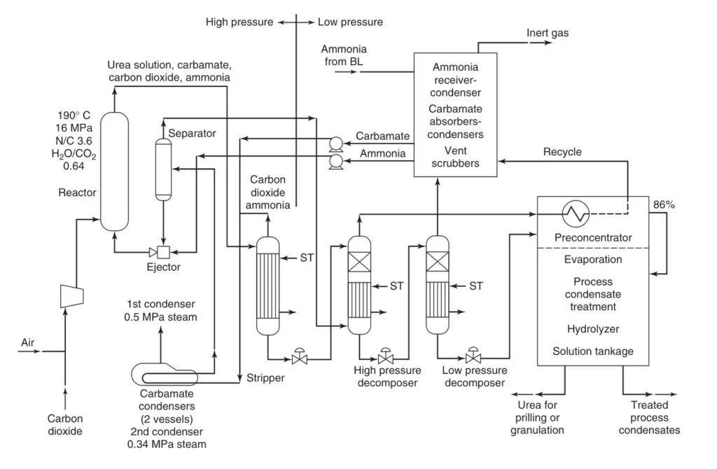
Thermal stripping removes CO2 from the synthesis solution more efficiently than CO2 stripping. The higher stripper temperatures limit the ammonia removal efficiency, however. The relatively high NH3/CO2 ratio and the lower stripper efficiency require a medium-pressure (1.8 MPa, 18 bar) and a low-pressure (0.4 MPa, 4 bar) recirculation section. The medium-pressure section contains a washing column, also called the medium-pressure absorber, and an ammonia/carbamate separating distillation column. They allow ammonia to return to the synthesis section in pure form. Saipem claims that this medium-pressure section gives great plant flexibility and allows operation over a wide range of NH3/CO2 ratios.
Because the ammonia recycle is pure, CO2 conversion in the synthesis matters more than NH3 conversion. Ammonia can be recycled without adding water, so this recycle does not shift the urea equilibrium unfavorably.
The synthesis section has a horizontal layout. An NH3-driven high-pressure ejector maintains circulation in the reactor–stripper–condenser loop. The stripped gas goes to one or two kettle-type high-pressure carbamate condensers in series and then to a high-pressure separator, and back to the reactor. The reactor runs at about 15 MPa (150 bar) with an NH3/CO2 molar feed ratio of about 3.5. The stripper off-gas is mixed with carbamate recycled from the medium-pressure and low-pressure recirculation sections, which resemble those of the total-recycle process.
The stripper is a falling-film type. Efficient thermal stripping requires 200–210 °C, which rules out stainless steel tubes. The first industrial plants used titanium tubes. Titanium eroded, so it was replaced at the end of the 1980s by bimetallic tubes. These have an external tube of 25-22-2 Cr-Ni-Mo stainless steel and an internal tube of zirconium.
Two newer stripper designs are available. In the full zirconium stripper, both lining and tubes are zirconium, which resists erosion and corrosion. The OMEGABOND tubes were developed with ATI Wah Chang (USA) and build on the experience with titanium strippers. They are made by extruding titanium (external) and zirconium (internal) billets together, which forms a metallurgical bond between the two metals and overcomes the erosion limits of full titanium tubes.
The plant has an efficient heat-exchange system that keeps the overall steam requirement low. Wastewater containing NH3 and urea undergoes desorption and hydrolysis to recover nearly all the NH3 and urea. The hydrolyzer operates at 3–3.5 MPa (30–35 bar), and its output can typically serve as cooling water make-up or boiler feed water. The urea solution is evaporated in one or two stages, depending on whether the product is prills or granules.
Saipem lists the following strengths: an efficient and reliable process with easy, safe operation and a high on-stream factor, and a high-quality product with low biuret and moisture content. The medium-pressure section buffers upsets in the high-pressure section and gives greater operating flexibility. The excess of ammonia and the possibility of blocking in the high-pressure section also support a high on-stream factor.
4.3. Toyo Engineering Corporation ACES21 process
The Japanese company Toyo Engineering Corporation (TEC) licensed variants of the conventional urea process until the 1980s. It then announced its own stripping technology, the ACES process (Advanced process for Cost and Energy Saving). The latest version is ACES21. The ACES processes use CO2 stripping in the synthesis section.
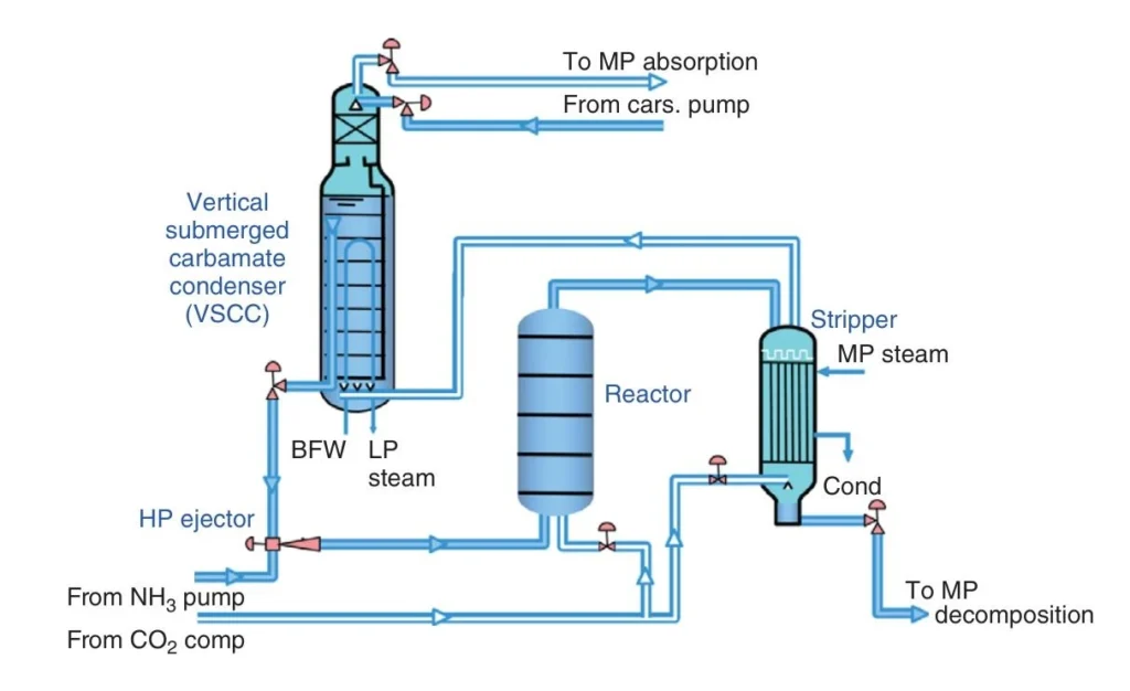
The synthesis section of ACES21 consists of a reactor, a stripper, a vertical submerged carbamate condenser and an ejector. Liquid ammonia enters the reactor through the ejector. Most of the CO2 goes to the stripper as stripping medium. The rest goes to the reactor, where it supplies passivation air and serves as a raw material for urea synthesis. Carbamate solution from the condenser is pumped into the reactor by the ejector, driven by high-pressure liquid ammonia. The urea solution leaving the reactor goes to the stripper, where unconverted carbamate decomposes thermally and CO2 stripping separates surplus ammonia and carbon dioxide. The stripped urea solution goes to an medium-pressure recirculation stage.
The stripped off-gas goes to the vertical submerged carbamate condenser. NH3 and CO2 condense on the shell side and form ammonium carbamate and urea. The tube side recovers the condensation heat as low-pressure steam. A packed bed at the top absorbs uncondensed NH3 and CO2 into recycle carbamate solution from the medium-pressure absorption stage. Inert gas from the top of the bed goes to the medium-pressure absorption stage. The ejector mainly drives the circulation of liquid and gas in the synthesis loop. The elevated position of the carbamate condenser adds driving force by gravity. Forced circulation allows a low-level layout.
As in all processes, process condensate and other urea–NH3–water waste streams go to a desorber–hydrolyzer. Its output can typically serve as cooling water make-up or boiler feed water.
TEC pioneered the use of duplex stainless steels in urea plants. Its latest development is the duplex steel DP28W, developed with Sumitomo Metal Industries Ltd. It is claimed to have greatly improved corrosion resistance compared with conventional duplex steels, and it passivates well in urea–carbamate solutions. This super duplex steel allows high-pressure vessels and pipelines to be smaller, lighter and more corrosion resistant.
5. Production of urea by other processes
Partial-recycle and once-through processes are older designs. They use a single reactor in the high-pressure synthesis section. They typically consume significantly more energy than modern urea technologies. New grassroots technologies are offered by Casale (Switzerland), NIIK (Russia), and WEC and JX (China).
6. Finishing processes (Solidification)
Urea processes deliver an aqueous solution containing 70–85 wt% urea. This solution can be used directly in nitrogen fertilizer solutions such as UAN, which is popular in certain regions. Evaporation or crystallization concentrates the solution for granular compound fertilizers and other products. Concentrated urea is solidified in essentially pure form as prills, granules, pastilles or crystals. Solid urea is cheaper to ship, store, distribute and use than the solution, and it is more stable.
6.1. Prilling
Prilling is declining, especially in export-oriented plants, because prills are of lower quality than granules. In a prilling plant, two-stage concentration turns the urea solution from the recovery section into a 99.6 wt% urea melt. The melt is pumped to the top of a 60–110 m cylindrical concrete tower and fed into a spinning bucket with a few thousand small holes. The emerging droplets solidify as they fall and are cooled by a forced or induced draft of air.
The fine dust formed mainly by sublimation leaves the tower top with the air and is an environmental problem. Prills must also stay small to solidify and cool properly within a practical fall height. Their crushing and impact strength are generally much lower than those of granules, which causes handling problems in the plant and during shipping. Stamicarbon introduced a seeding system that improved the impact strength of prills. Adding formaldehyde slightly increases the crushing strength and suppresses caking during storage.
6.2. Granulation
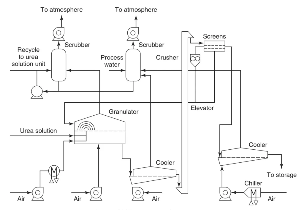
Almost all new export-oriented urea plants produce granules. Most plants use the processes of thyssenkrupp Fertilizer Technology (formerly Hydro-Agri), Stamicarbon, Toyo Engineering Corporation or Green Granulation Technology. They differ mainly in the type of sprayers and the movement of the fluid bed.
6.3. Pastillation
IPCO (formerly Sandvik Process Systems) developed the Rotoform urea pastillation process, an ideal way to solidify molten urea and other fertilizers. Its flexibility allows standard fertilizer urea and fertilizer specialties containing additives such as ammonium sulfate, potassium chloride, zinc oxide or sulfur. The same equipment can produce high-purity urea for technical or pharmaceutical use. The process has low energy consumption and high environmental friendliness, which make it particularly suitable for urea pastillation. A typical line has a capacity of 125 metric tons per day.
7. Downstream fertilizer derivatives: Urea-ammonium nitrate solutions
Some countries, currently mainly in Europe and the United States, have a market for liquid urea–ammonium nitrate (UAN) solutions containing 32% N. A partial-recycle stripping process is the best and cheapest system for this product. The unconverted NH3 from the stripped urea solution and the reactor off-gas is neutralized with nitric acid.
The ammonium nitrate solution formed is mixed with the urea solution from the stripper bottom to give a 32–35 wt% UAN solution. This route reduces investment costs drastically, since evaporation, finishing (prilling or granulation) and wastewater treatment are not needed.
8. Future trends
Demand for urea has risen steadily. All licensors have designed plants with higher capacities, driven by economies of scale. Other trends are stricter environmental regulations and urea product specialties, such as multinutrient and higher-efficiency urea fertilizers.
References
1. Meessen, J. “Urea synthesis.” Chem. Ing. Tech., 2014, 86 (12), 2180–2189. DOI: 10.1002/cite.201400064.
2. Brouwer, M. Urea. In Kirk-Othmer Encyclopedia of Chemical Technology; John Wiley & Sons, Inc., 2019. DOI: 10.1002/0471238961.2118050113012218.a01.pub3.
3. Meessen, J. H. Urea. In Ullmann’s Encyclopedia of Industrial Chemistry; Wiley-VCH, 2010. DOI: 10.1002/14356007.a27_333.pub2.
4. Masjedi, S. K.; Kazemi, A.; Moeinnadini, M.; Khaki, E.; Olsen, S. I. “Urea production: An absolute environmental sustainability assessment.” Sci. Total Environ., 2024, 908, 168225. DOI: 10.1016/j.scitotenv.2023.168225.
5. Ding, J., Ye, R., Fu, Y. et al. Direct synthesis of urea from carbon dioxide and ammonia. Nat Commun 14, 4586 (2023). https://doi.org/10.1038/s41467-023-40351-5